
How to Specify a Shell-and-Tube Heat Exchanger
A good specification gives suppliers enough information to size an exchanger, compare construction options and prepare a quote. This guide covers the process data, mechanical requirements and documentation to include in your request.
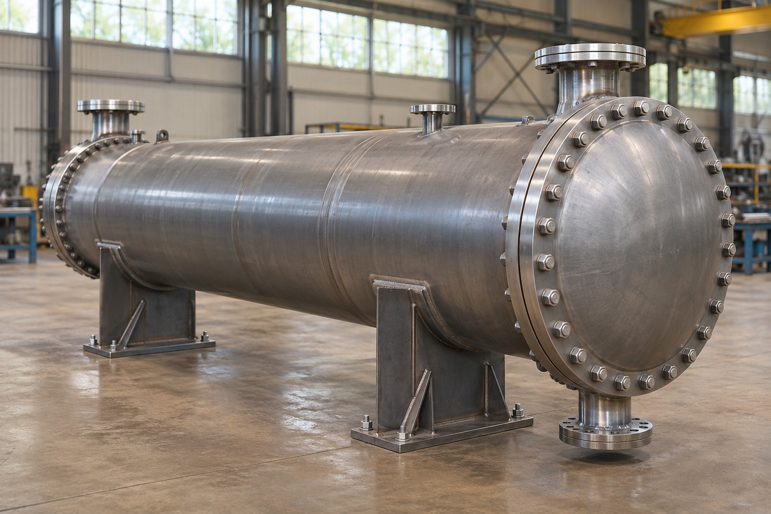
Why the specification decides the outcome
A shell-and-tube heat exchanger is not a catalogue item you pull off a shelf. Two exchangers with the same shell diameter can differ by a factor of three in heat transfer area, pressure drop, and price — depending on the fluids, temperatures, and pressures they were designed for.
That is why a supplier cannot price “a 12-inch exchanger, about six feet long” any more than a builder can price “a house, about this big.” The thermal design — done properly in rating software such as HTRI — needs real process data. Complete data gets you a firm, comparable quote. Incomplete data gets you a round of follow-up questions, a padded estimate to cover the unknowns, or a design with so much safety margin built in that you pay for steel you never needed.
The good news: specifying an exchanger is mostly a matter of answering ten questions well. None of them requires specialist software. Most of the answers are already sitting in your process flow diagram, your heat and material balance, or your plant historian.
The 10 things every specification needs
Send these ten items and a designer can rate your exchanger, select a construction type, and price it without coming back to you. Where you genuinely don’t have a number, say so — a stated unknown is far easier to work with than a silent one.
-
Both fluids, clearly identified
Name each fluid and say which stream is being heated and which is being cooled. “Cooling tower water” is workable; “process fluid” is not. If a stream is a mixture, give the composition. If it changes phase — condensing steam, boiling refrigerant, a vapourising process stream — say so, because a phase change completely changes the design. Flag anything corrosive, toxic, or fouling-prone now, not later.
-
Flow rate for each stream
Give the flow of both fluids in consistent units — lb/hr, gpm, or kg/h are all fine. If flow varies, give the normal, minimum, and maximum cases, and say which case the exchanger must guarantee. A unit sized only for average flow will disappoint you on the day the plant runs at full rate.
-
Inlet and outlet temperatures — all four
Each stream needs an inlet temperature and a required outlet temperature. Together with the flow rates, these four temperatures define the duty — the amount of heat, in BTU/hr, the exchanger has to move. If only three temperatures are known, the fourth can be calculated from the duty, but one side of the equation has to be pinned down.
-
Operating pressure — and design pressure
State the operating pressure of each side, and the design pressure and design temperature the vessel must be built to. These are not the same thing: design conditions set the wall thickness, flange ratings, and code calculations. Leaving them blank forces the designer to guess — and guesses, for safety, always go up, along with the price.
-
Allowable pressure drop for each side
How much pressure can each stream afford to lose passing through the exchanger? This single number drives tube size, baffle spacing, nozzle sizes, and pass arrangement. If your pump or compressor has limited head available, the allowable pressure drop is a hard limit, not a preference — say so clearly.
-
Physical properties at operating conditions
Density, viscosity, specific heat, and thermal conductivity for both fluids, at the actual operating temperatures. For common fluids — water, steam, standard oils — the designer’s software already has these. For proprietary process streams, only you have them, and viscosity in particular can change a design completely. Properties at the wrong temperature are worse than no properties at all.
-
Fouling factors and how the unit will be cleaned
Every exchanger fouls over time; the question is how fast, and how you plan to clean it. State the fouling allowance you want designed in (industry practice follows TEMA fouling resistances for common services), whether the bundle must be removable for cleaning, and whether you clean chemically or mechanically. A dirty service in a fixed-tubesheet unit that can’t be opened is a problem designed in from day one.
-
Materials of construction
Specify the materials for shell, tubes, tubesheets, and channel — or describe the corrosion environment well enough for the designer to recommend them. Carbon steel, stainless grades, copper alloys, titanium, and graphite all have their place, and the tube material is usually the first decision because the tubes are the thinnest, hardest-working part of the exchanger. See the materials section below.
-
Size, orientation, and nozzle constraints
Where is this unit going? Give the available plot space and maximum length, whether it mounts horizontally or vertically, any weight limit on the foundation or structure, and the nozzle sizes, ratings, and orientations your piping needs. A design that performs beautifully but is two feet too long for the pipe rack is not a design — it is a re-design waiting to happen.
-
Codes, standards, and documentation required
Name the design code (normally ASME Section VIII, Division 1), the TEMA class, and any company or industry specifications that apply — plus the paperwork you need with the unit: code stamping and registration, material test reports, drawings for approval, or a full data book. Documentation is cheap when it is specified up front and expensive when it is requested after fabrication. See the codes section below.
Don’t have all ten? Send it anyway.
Plant teams often hold off enquiring until every number is nailed down — and lose weeks. Send the duty, the fluids, and the temperatures you do have, and mark the rest “to be confirmed.” An experienced designer can rate the exchanger on stated assumptions, flag exactly which missing numbers could change the selection, and keep your project moving while you confirm them.
A filled-in example data sheet
This illustrative oil-cooler example shows the format of a request for quotation. Confirm the actual process data and operating limits for your project.
| Item | Hot side (shell side) | Cold side (tube side) |
|---|---|---|
| Fluid | Lube oil, ISO VG 46 | Cooling tower water |
| Flow rate | 120 gpm | 150 gpm |
| Temperature in / out | 180 °F in, 130 °F out | 85 °F in; outlet temperature to be calculated |
| Operating pressure | 150 psig | 90 psig |
| Design pressure / temp. | 200 psig / 250 °F | 150 psig / 200 °F |
| Allowable pressure drop | 10 psi | 8 psi |
| Fouling / cleaning | Light oil fouling; chemical clean | Treated tower water; bundle to be removable for mechanical cleaning |
| Materials | Carbon steel shell; admiralty or stainless tubes to suit tower water — designer to recommend | |
| Construction & codes | Horizontal, TEMA Class C, ASME Section VIII Div. 1 stamped; maximum overall length 12 ft; nozzles 3 in. shell side, 4 in. tube side | |
The example identifies the known operating conditions, pressure-drop and space limits, and the cleaning requirements. It leaves the cooling-water outlet temperature for the designer to calculate from the heat balance and asks for a tube-material recommendation.
Which fluid goes on which side?
You don’t have to decide this — the designer will — but if your plant has a preference, state it and say why. The usual rules of thumb are:
- Tube side for the corrosive fluid, so only the tubes, tubesheet, and channel need the expensive alloy — not the whole shell.
- Tube side for the dirty, fouling, or scaling fluid, because tube interiors are far easier to clean mechanically.
- Tube side for the high-pressure fluid, because a small-diameter channel handles pressure more cheaply than a large shell.
- Tube side for the smaller flow, and for fluids where precise temperature control matters.
- Shell side for viscous fluids, which transfer heat better in the cross-flow pattern around the tubes.
- Shell side for condensing vapours and for the larger flow in most liquid–liquid services.
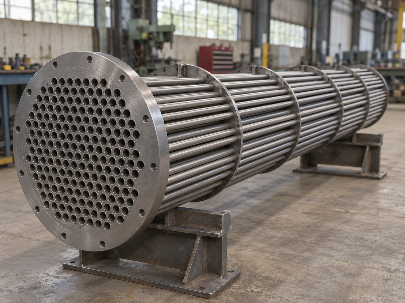
TEMA types, in plain English
Exchangers are described by a three-letter TEMA designation — front head, shell, and rear head, in that order. You will see these letters on drawings and quotes, and the rear-head letter is the one that most affects price and maintainability, because it decides how the exchanger handles thermal expansion and whether the bundle can be pulled for cleaning.
| Construction | Common TEMA types | Best for | Watch out for |
|---|---|---|---|
| Fixed tubesheet | BEM, AEL, NEN | Clean fluids, modest temperature difference between the two streams, lowest first cost | The bundle cannot be removed, and shell-side mechanical cleaning is not possible. Large temperature differences stress the tube-to-tubesheet joints unless an expansion joint is fitted. |
| Floating head | AES, AET | Dirty services, large temperature differences, and any duty where the bundle must come out for cleaning or replacement | Highest cost of the common types, and a larger shell for the same tube count — but it is the workhorse of refinery and chemical plant service for a reason. |
| U-tube | AEU, BEU | High temperatures and pressures, and thermal expansion problems — each tube is free to grow independently | The bundle is removable, but the inside of the U-bends is hard to clean mechanically, and a failed tube in the bundle is harder to replace. |
| Kettle reboiler | AKT, BKT | Boiling a liquid and drawing off vapour, typically at the base of a distillation column | Needs level control and vapour disengaging space — it is a specialist selection, so describe the boiling duty in full. |
Also name the TEMA class: Class R for severe refinery and petroleum service, Class C for general commercial service, and Class B for chemical process service. The class sets mechanical details such as corrosion allowance, tube pitch, and minimum thicknesses — which is why the same duty can be quoted at noticeably different weights and prices against different classes.
Choosing materials
Material selection is a corrosion decision first and a cost decision second. The cheapest material that survives the service is the right one — and “survives” has to account for both fluids, cleaning chemicals, and start-up and upset conditions, not just normal operation.
| Material | Typically chosen when | Notes |
|---|---|---|
| Carbon steel | Services are non-corrosive — oils, hydrocarbons, steam condensate | Lowest cost and easy to fabricate. Needs a corrosion allowance where any attack is expected. |
| Stainless steel (304 / 316) | Corrosive process streams, food and pharmaceutical duties, treated waters | 316’s molybdenum content improves resistance to chloride pitting over 304 — relevant with cooling tower and coastal waters. |
| Copper alloys (admiralty brass, 90/10 Cu-Ni) | Water services, especially seawater and brackish cooling water (Cu-Ni) | Excellent thermal conductivity. Check compatibility with ammonia and sulphides, which attack copper alloys. |
| Titanium | Seawater, chlorides, and oxidising corrosive services defeat stainless steels | High first cost, very long life in the services that suit it. Often the cheapest option over the life of the plant. |
| Graphite and silicon carbide | Highly corrosive chemicals such as hydrochloric acid, where metals fail quickly | Graphite exchangers — including the SGL Carbon lines Keller represents — are the standard answer for corrosive chemical and HCl service, but they need handling and pressure limits respected. |
| High alloys (Duplex, Hastelloy, Inconel) | Hot, aggressive, or mixed-acid services exceed stainless capability | Specify from corrosion data or testing, not from habit — the cost step is significant and sometimes avoidable with a different construction. |
If you are unsure, describe the fluids, concentrations, temperatures, and any history — “the last bundle lasted four years and failed by pitting under deposits” is exactly the kind of information that leads to a better selection than guessing a grade.
Codes, standards and testing
- ASME Boiler and Pressure Vessel Code, Section VIII, Division 1 — a pressure-vessel design and fabrication code. Confirm the applicable code, edition and jurisdictional requirements for your installation. State whether an ASME U stamp or National Board registration is required.
- TEMA standards — the Tubular Exchanger Manufacturers Association standards covering mechanical design, tolerances, and the class system described above.
- API 660 — commonly specified on top of TEMA Class R for refinery shell-and-tube service.
- HTRI rating — Keller rates thermal designs in HTRI software, the industry-standard tool, so the performance prediction behind your quote is checkable rather than a rule of thumb.
- Testing and inspection — state the required tests, examination methods and inspection hold points in the request. The applicable code and project specifications govern testing requirements.
The three trade-offs behind every design
Every exchanger design is a balance of three things. Knowing the balance exists helps you read quotes intelligently — and explains why the lowest-price unit is not always the cheapest to own.
1. Area versus pressure drop
Pushing fluid faster improves heat transfer and shrinks the exchanger, but pressure drop rises roughly with the square of velocity, and pumping costs money every hour the plant runs. Your allowable pressure drop (item 5) is where this trade-off gets settled.
2. Fouling margin versus overdesign
Designing in fouling resistance means extra area, which costs money up front and — because velocities fall — can sometimes make fouling worse. The right margin comes from honest information about your fluid and your cleaning interval (item 7), not from doubling the area “to be safe.”
3. First cost versus cleanability
A fixed-tubesheet unit is cheaper to buy than a floating-head unit of the same duty. If your service fouls and the bundle has to be cleaned twice a year, the floating head pays for itself quickly in downtime alone. Match the construction to the cleaning reality.
Specifying a retrofit or replacement
Replacing or re-rating an existing exchanger needs everything above, plus what you know about the unit already in the line:
- The existing manufacturer, model, serial number, and TEMA type — all on the nameplate. A phone photo of the nameplate is genuinely useful.
- The original data sheet or general arrangement drawing, if you have them.
- How the existing unit performs now: actual flows and all four temperatures, measured at the same time, plus the pressure drop if you have gauges.
- Why it is being replaced — fouled, corroded, leaking, or simply undersized for a duty that has grown.
- The fixed constraints: nozzle locations and sizes that must match existing piping, and the maximum footprint the replacement can occupy.
- Whether you want a like-for-like replacement, a re-rate for a new duty, or a re-design that fixes the original unit’s weaknesses.
Keller provides thermal design for retrofits as well as new installations, so an existing exchanger can often be assessed for a different duty before you commit to replacing it.
Mistakes that slow down quotes
These are the gaps and errors that most often send an enquiry back with questions instead of forward with a price:
- Missing outlet temperatures. Flow rates alone don’t define a duty. Without temperatures, there is nothing to design to.
- No allowable pressure drop. The designer has to assume one — and the assumption will either inflate the unit or produce a design your pump can’t push through.
- Properties at the wrong conditions. Viscosity quoted at room temperature for a fluid that runs at 300 °F can change the tube count by half.
- Mixed-up units. gpm versus lb/hr, psig versus psia, °F versus °C. State the units on every number, every time.
- Operating pressure given, design pressure forgotten. Fabrication cannot be priced properly without design conditions.
- No mention of fouling or cleaning. This decides the construction type. Leaving it out invites the cheapest construction — which may be the wrong one for your service.
- Plot space discovered late. Mentioning the 10-foot length limit after the 14-foot design is quoted wastes everyone’s week, including yours.
- “Same as the last one” — with a different duty. If flows or temperatures have changed since the last purchase, the old drawing is background, not a specification.
Copy-and-send RFQ checklist
Copy this checklist into your next request for quotation and fill in what you can. Even a half-completed version, honestly marked, will get you a faster and firmer quote than a paragraph of prose.
Shell-and-tube exchanger — RFQ checklist
- Service / tag number and what the exchanger does in the process
- Hot fluid name and composition — and cold fluid name and composition
- Phase of each stream: liquid, vapour, or changing phase
- Flow rate of each stream (with units), plus min / normal / max if it varies
- All four temperatures: hot in, hot out, cold in, cold out
- Operating pressure of each side
- Design pressure and design temperature of each side
- Allowable pressure drop for each side
- Physical properties at operating temperature (or ask the designer to use software values for standard fluids)
- Fouling factors required, cleaning method, and whether the bundle must be removable
- Preferred shell-side / tube-side arrangement, if any, and why
- Materials of construction — or a description of the corrosion environment
- TEMA type and class if specified; ASME VIII Div. 1 stamp required? (yes / no)
- Orientation (horizontal / vertical), maximum length and footprint, weight limits
- Nozzle sizes, ratings, and any fixed piping orientations
- Documentation required: approval drawings, material reports, data book
- For a replacement: nameplate photo, existing drawings, and current measured performance
- Delivery site and required delivery date
What happens after you send it
With a complete specification, the process is straightforward. Keller rates the duty in HTRI, selects a TEMA construction and materials that suit the service and the cleaning reality, and matches the design to the manufacturers we represent — including large-diameter and custom alloy fabrication through Gaston Fabrication, and graphite and silicon carbide exchangers through SGL Carbon for corrosive duties where metal is the wrong answer. You receive a priced proposal with the thermal design behind it, so your team can check performance, pressure drop, and construction against your specification line by line.
If your specification has gaps, you will get specific questions back — not a padded price. That is deliberate: a quote built on stated assumptions you can review is worth more than a fast number built on guesses you can’t.
Discuss your thermal design project
Keller & Associates helps engineering firms and plant teams source heat exchangers, process heaters and thermal fluid systems, and provides shell-and-tube thermal design for new installations and retrofits. Send your data sheet — complete or not — and we’ll take it from there.